
|
Search | FAQ | US Titles | UK Titles | Memories | VaporWare | Digest | |||||||
| GuestBook | Classified | Chat | Products | Featured | Technical | Museum | ||||||||
| Downloads | Production | Fanfares | Music | Misc | Related | Contact | ||||||||
| Instructions to Install an IR Remote on F/G CED Players | ||||||||||||||
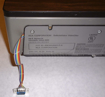
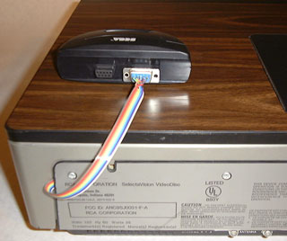 This picture shows a D-Subminiature 9-pin connector coming out of the back of an SFT100 VideoDisc Player. This is used in conjunction with an Atari joystick or a Sega IR controller and receiver (the black box on top of the player) to provide remote control functions on F/G CED players. This interface works with all F/G CED players including the SGT075 (with the addition of four diodes). On the SGT250 the interface can co-exist with the factory installed remote circuitry, and could be installed if you can't find an original remote, or want remote access to page mode, which was not provided by RCA. The remainder of this page contains the instructions for installing this interface. If you arrived at this page via a web search, be sure to first read the Introductory Page for background information on this remote control interface.
Although this circuit is simple, I would classify the project at an intermediate skill level, since you are interfacing to a complex electronic device (the CED player), and building your own circuit from prototyping board in the process. If you have never touched a soldering iron, don't use this project as a learning tool. Rather get an inexpensive electronic kit, and use that to learn soldering.
Here are my standard guidelines for performing any electronic work on a CED player:
To perform this installation you need a low wattage soldering iron suitable for circuit board use and some basic hand tools. In addition the following parts from Jameco Electronics are needed to build the interface:
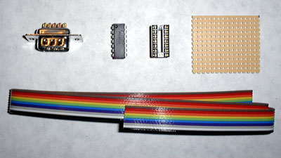 (1) We'll start by assembling the interface, so check to make sure you have all the kit contents necessary to build the circuit. This includes one D-Subminiature 9-pin connector, one 7407 integrated circuit, one 14-pin IC socket, a 1.5" x 1.25" piece of protoboard, and a 26" length of color-coded 10-conductor ribbon cable. Other items required include a 25 Watt soldering iron, thin rosin core solder, a wire stripper, a 1/4" hex driver, and a medium Phillips driver.
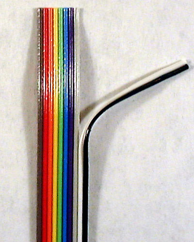 (2) Take a look at the 10-conductor ribbon cable. It is color-coded using the standard coding scheme except the first conductor on the cable is brown, for the numeral 1, because black (which normally appears first) is for the numeral 0, but cable pins are numbered starting with "1", not "0." Proceeding from left to right we have these colors and pin assignments used on the circuit diagram for the remote control interface:
Since only 8 pins of the D-Subminiature connector are used, but the ribbon cable has 10 wires, the extra white and black wires can be peeled off as shown here and set aside. These will later be used for +5 Volt power and ground connections. To peel the two wires off, make a separation between the gray wire and the white wire with your fingernail and then simply pull the two wires as a unit off the entire 26 inch length of the ribbon cable. After they have been peeled off, make another separation between the peeled off white wire and peeled off black wire and completely separate them.
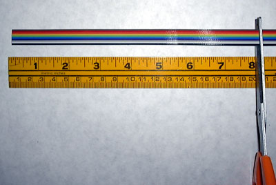 (3) The supplied ribbon cable is 26 inches long, but only an 18 inch length is needed to comfortably reach from the circuit board to the outside of the CED player. Cut off a 8 inch piece of the ribbon cable for the connections inside the CED player. The cutter on some wire strippers or an ordinary scissors can be used to make the cut. After cutting, peel each of the individual wires off the 8 inch piece, but leave the 18 inch piece intact. The individual 8 inch wires will go to solder points inside the CED player, while the 18 inch intact ribbon connects to the D-Subminiature connector.
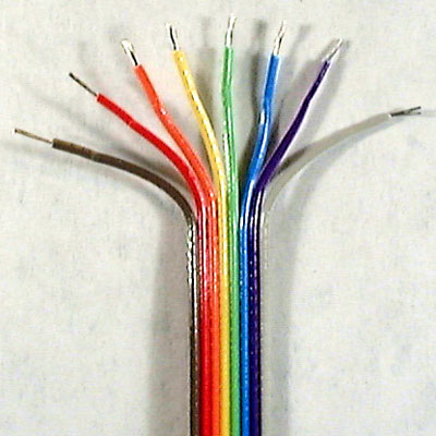 (4) This picture shows one end of the 18 inch ribbon cable with the eight remaining wires peeled back about an inch and the insulation stripped off to about 1/8" or 3/16." This is done to both ends of the cable, as one end will be soldered to the D-Subminiature connector and the other to the 1.5" x 1.25" circuit board. You'll want to strip a little less insulation off the D-Sub end of the cable, as the wires on that end go straight into the connector without wrapping around.
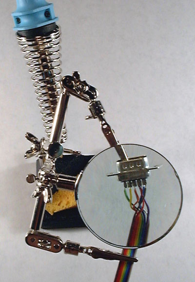 (5) This is a Third Hand tool, which is very useful to hold the D-subminiature connector and ribbon cable leaving your hands free to hold the soldering iron and solder. Later it can be used to hold the other end of the ribbon cable and the 1.5" x 1.25" circuit board while making those solder connections. On the D-Subminiature connector make the solder connections beginning with the brown wire and proceeding wire-by-wire to the final gray wire. Note that the circuit diagram shows the D-Subminiature connector looking into the pin side of the connector, when you're looking into the opposite solder side the pin numbering is reversed. Most of these connectors also have the pin numbers printed inside the pin side of the unit. Here are the wire color/pin number assignments:
When you have finished soldering the connector, only Pin 9 should be left blank, all other pins on the D-Sub should have one wire attached. Visually check the D-Sub against the circuit diagram color coding.
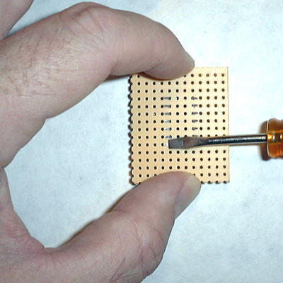 (6) Here the IC socket is being installed into the approximate center of the 1.5" x 1.25" piece of protoboard. If you are making this interface for an SGT075 player, you'll want to install the socket off to one side to make room for the four diodes that are only required with that particular player.
To secure the IC socket hold the board down on a tabletop with the table firmly pressing the IC socket into the protoboard. With a small blade driver bend each of the 14 leads out towards the edge of the board as shown. These bent leads will become the solder joints for the board.
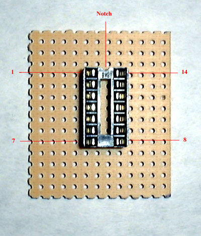 (7) This picture shows the top of the circuit board with the integrated circuit socket installed. Most IC sockets have a notch cut out to indicate the top of the socket. The IC chips themselves also have this notch, so you know the proper orientation to insert them into the socket. The socket could actually be orientated either way, but this is never the case for integrated circuits, so make use of the notch protocol on the socket, or if it lacks a notch, choose one end as the top for further work.
The pins on the socket are numbered from 1 to 7 down the left side, and 8 to 14 up the right side. IC's are always drawn looking down at the top of the chip, so that's the orientation on the remote control circuit diagram. But remember the soldering is done from the bottom side, and looking into the bottom, left and right are reversed.
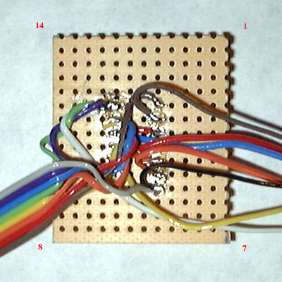 (8) Here is the bottom of the board with all wires soldered according to the circuit diagram. Refer to the diagram and the following list to determine the wire colors and functions:
The input wires to the IC all come from the eight conductor ribbon cable, while the output wires are the individual wires peeled off in Step 3. The number in parentheses refer to the pin numbers on the D-Sub where the input wire originated. The Ground and +5 Volt pins on the IC serve as juncture nodes between the source inside the player and the pins on the D-Sub that require ground and power. These are the white (+5 V) and black (Gnd) wires peeled off in Step 2. Note that for each input on the IC a matching color wire is soldered to the output. I like this color coding because you can look at a wire soldered inside the player and visually trace it to the D-Sub connector. To solder the wires to the IC socket form a small hook in the end of each wire and loop it over the pins on the socket.
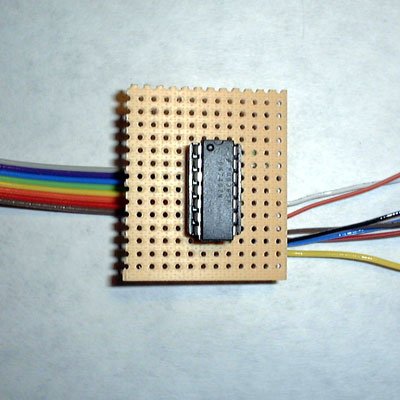
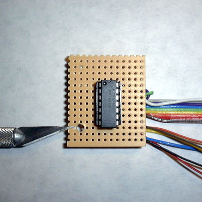
 (9) Here is the completed board now only requiring the 7407 IC and installation and mounting inside the CED player. The long white and black wires can be shortened later on just prior to soldering them inside the CED player.
 (10) The 7407 Hex Buffer/Driver integrated circuit is a robust chip not particularly sensitive to static electricity, so it's safe to insert it into the socket now. If the IC were inserted later on, after the board has been mounted in the player, the force required for insertion might crack the protoboard where it is attaches to a player screw. The pins on the IC may need to be squeezed inward slightly to fit them into the socket, and the chip should be seated all the way down into the socket. Note that the top of the IC has a notch similar to the IC socket, and Pin 1 of the IC is marked with a dimple.
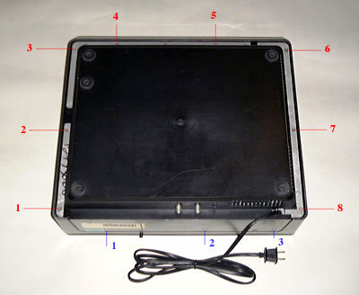 (11) We are now ready to remove the cover from the CED player to gain access to the solder points inside and install the circuit board. Place the player upside down on a soft surface and remove the eight 1/4" hex head screws from the bottom. Next remove the three medium Phillips screws from the back of the player. Invert the player and lift the cover off.
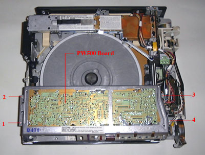 (12) With the cover off, the PW500 circuit board above the turntable can be seen. It is to the other side of this board that the wires from the remote interface will be soldered. To loosen the board remove the four 1/4" hex head screws indicated in the picture. These screws are a slightly different size than those removed from the bottom of the player, so keep them separate.
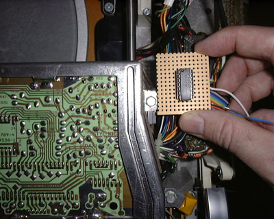 (13) This picture shows the remote interface board being held next to Screw No. 3 from the previous step. This screw is an ideal mounting position for the board. By holding the board over the screw or screw hole, you can determine which small hole on the protoboard needs to be enlarged to make this installation possible.
 (14) Here a razor blade is held next to the enlarged hole on the remote interface board. The point of a razor blade can be used in a circular fashion to gradually enlarge the hole until it is big enough for Screw No. 3 to be rotated in and out (but not so large that the screw slides freely through the hole). This step should be performed before the board is soldered to keep particles produced by the enlarging process from falling into the player.
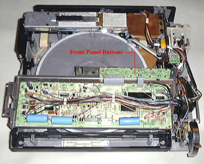 (15) The screws securing the PW500 board were removed in Step 12 so the board could be worked on from the other side (which is really the top of the board). Lift the board up and turn it around, placing it back down in about the same position, but inverted. The extension board which contains the front panel switches and is attached by two gray ribbon cables is where the outputs from the 7407 integrated circuit will be soldered.
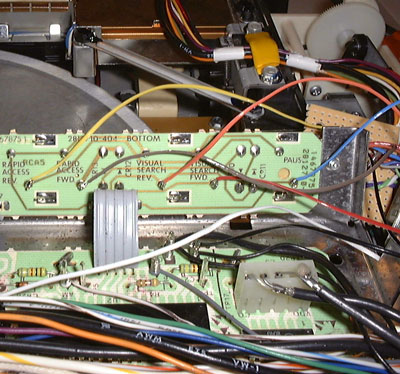
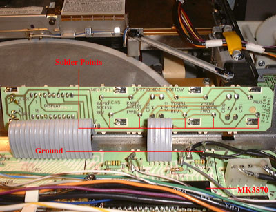 (16) This picture shows a closeup of the switch extension board with the solder points to the five switches indicated. Notice that the function of each switch is conveniently printed on the circuit board. These solder point are rigid wires extending about 1/8" outward from the board, so they make easily accessible solder connections. A ground post below the extension board serves as the Gnd connection for the remote control interface. And further below that the actual MK3870 microprocessor can be seen.
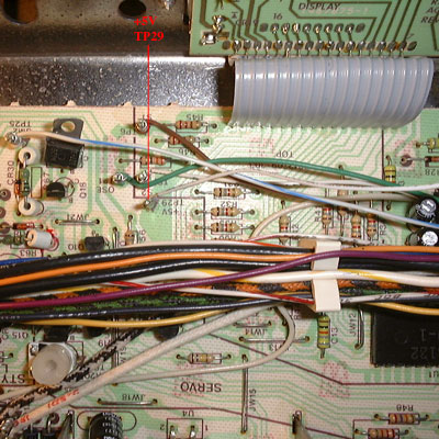 (17) Shown here is the white wire from the remote interface protoboard soldered in place at +5V TP29 (Test Point No. 29) on the main PW500 circuit board. The white wire will be longer than necessary, so after shortening it, make a loop in the end that will fit over the test point metal post. Solder the loop in place a little above the bottom of the post.
 (18) Here all the wires have been soldered to the switch contacts inside the CED player. The colors from left to right plus the power and ground connections are:
The connections to the switches are made by forming a small loop in the end of each wire and soldering this loop at the base of each switch post. On the SGT075 player only the visual search switches are present, so with this player model only, the remaining wires will need to be directly soldered to the MK3870 microprocessor.
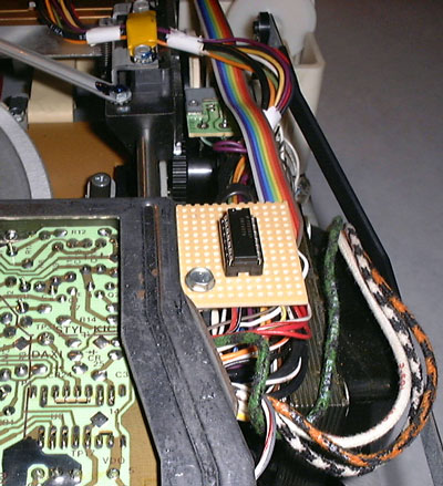 (19) Invert the PW500 board assembly and place it back into the correct position on top of the player chassis, while carefully routing the remote interface board out the right-hand side. Attach screws 1, 2, and 4 removed in Step 12. Now attach screw 3 through the hole in the remote interface board, but tighten it down with moderate force, lest the surrounding protoboard material cracks. Notice the path of the ribbon cable to the back of the CED player.
 (20) Route the ribbon cable so it exits just to the side of screw 3 on the back of the player. In this position the cover can be put back on, as the ribbon cable is flat enough not to be damaged by the closed cover. Secure the three Phillips screws to the back of the player that were removed in Step 11. Invert the player on a soft surface and replace the eight 1/4" hex screws also removed in Step 11. Turn the player upright and it's ready for use.
Enjoy the new remote control capabilities of your CED player!